Question: What are the differences in the two receiver display modes on the 3000 Series 4th Generation wireless system?
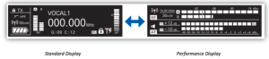
Answer: The 3000 Series ATW-R3210 receiver display has two viewing options. When you power up the receiver the standard operating mode is visible. This mode is helpful for setting up the wireless system. Turning the control dial will display the performance view, which emphasizes the audio and RF metering.
The standard receiver display includes information that is useful while setting up the system. On the left side of the display, the RF signal level and any connected transmitter information are displayed. When an adequate RF signal is present and registered on the RF signal level meter, the transmitter’s battery level and transmission power level is shown. Additionally, the A or B above the RF meter is highlighted, indicating which antenna the receiver is registering as the strongest signal at that moment. The center section in the standard operating mode includes the receiver name (if programed by the user), the frequency the receiver is currently tuned to, and the frequency’s corresponding group and channel (used during frequency coordination and automatic frequency scans). The AF meter on the right side of the display can be set to show the audio output level of the receiver or transmitter. Additionally, the antenna input power indicator appears in the lower right corner of the display when the antenna power is engaged to power up active devices such as powered antennas or active splitters or combiners.
From the receiver menu screen you can also make the following changes:
- Set the indicator – frequency, group/channel, or receiver name – to be featured in the center of the display
- Set the backup frequency
- Lock out receiver controls
- Edit the user groups and channels
- Engage the 12V DC antenna power
- Check system firmware version
- Reset receiver to factory default settings
The performance mode focuses on RF and AF levels while the wireless system is in use. The top section in this mode shows the receiver’s RF level on the horizontal plane. Additionally, the power of the connected transmitter is displayed. To troubleshoot and monitor the RF signal, press the BACK button, which will engage the RF meter minimum hold level marker. This will display a line through the RF signal to indicate the lowest RF signal registered by the receiver. If the RF level dips below the marker position, the marker will move with it. To reset the minimum hold level, press the BACK button again.
The lower section in the performance mode displays two audio levels. The top of the two is the transmitter’s audio output level to the receiver, the bottom is the receiver’s audio output level. Just to the left of those two meters is the connected transmitter’s audio gain setting, as well as the receiver’s audio output setting. These indicators are helpful for setting up the wireless audio gain structure. If the audio from the transmitter to the receiver is too high and distorting, turning down the audio output of the receiver will not resolve the issue and clear up the audio. The transmitter gain setting would need to be adjusted in this instance. Likewise, if the audio signal is too low, you may note whether the transmitter level or the receiver audio level needs to be adjusted to maintain proper gain structure.
The speaker icon is visible on both the standard and performance views on the receiver display. When the transmitter is muted or the receiver does not have an adequate signal from the transmitter, the speaker icon will appear with a slash through it. This denotes that the audio circuit in the receiver is muted. To unmute the audio circuit in the receiver, make certain the transmitter is above the receiver’s squelch level and is transmitting a strong RF signal to the receiver, and that the transmitter is not in the muted state.
Watch the video below for additional information on using the receiver display modes:


.webp)