Question: What is the Difference between the Balanced and Unbalanced Dual-Mono settings on the System 10 Camera-Mount Wireless System?
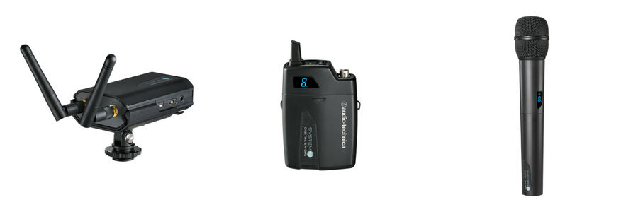
Answer: The ATW-R1700 receiver, which is part of the System 10 Camera-Mount Digital Wireless System, has a single audio output jack that accepts the 3.5 mm (1/8") audio cable that is included in the package. An audio output selector switch allows the user to choose between a balanced mono signal and an unbalanced dual-mono signal, making the system usable with most cameras and recording devices utilizing a 3.5 mm microphone input jack. For devices utilizing a single balanced professional XLR-type microphone input jack, an optional balanced 3.5 mm to XLR (male) output cable, the AT8350, is available.
Most consumer audio and video equipment today, such as cameras and portable audio recorders, use a single unbalanced 3.5 mm stereo mini-jack for connecting an external microphone. Prosumer (or semi- professional) equipment will often have this type of jack as well and, in some cases, may offer an additional balanced XLR-type microphone jack. The 3.5 mm jacks on prosumer equipment can be the unbalanced stereo type or the balanced type carrying a mono signal. Professional-grade equipment will typically have a balanced XLR-type microphone jack only, and quite often there will be more than one, permitting the use of multiple microphones simultaneously.
It is important to note that a 3.5 mm audio connection can be configured in many ways. These include an unbalanced mono configuration, where the signal is carried on the tip of a tip-sleeve plug; an unbalanced stereo configuration, where the left side of the signal is carried by the tip and the right side is carried by the ring of a tip-ring-sleeve plug; an unbalanced dual-mono configuration, where the same signal is applied to both the tip and the ring; and a balanced configuration, where the Audio+ (positive) signal is carried by the tip and the Audio- (negative) signal is carried by the ring. In all these configurations, the sleeve serves as the ground. The most common configuration, which many of us are familiar with, is the stereo configuration used for connecting stereo headphones to the stereo headphone jack on a music player for casual listening or to the jack on a video camera or portable audio recorder for monitoring the audio as it is being recorded. Like the headphone jack, the 3.5 mm microphone jack on equipment today is typically wired as a stereo connection as well. The jack is wired so that the signal from the left side of a stereo microphone appears on the tip of the jack and the signal from the right side appears on the ring. The tip carries the signal to the left speaker and the ring carries the signal to the right speaker, and a true stereo signal is produced as a result. A stereo signal places different information on each speaker to create the stereo effect.
If a mono microphone is connected to a stereo jack, the mic audio will appear on only one side of the jack, the left side (or the tip), and sound will be produced only by the left speaker in a left/right stereo speaker arrangement. Instead of no sound being produced by the right speaker, the user will often hear some amount of hiss. Audio-Technica has addressed this problem by wiring the 3.5 mm audio cable included in the System 10 Camera-Mount package in a dual-mono wiring scheme. Because the signal appearing at the audio output jack on the wireless receiver is a mono signal, the cable has been wired to place the signal on both the tip and the ring of the cable’s plugs. This is known as dual-mono because it is the same exact mono signal being placed on both the left (tip) and right (ring) speakers. Because the dual-mono wiring scheme places the same information on each speaker, it is not possible to produce a stereo effect, but you do get an audio signal on both speakers and without any hiss.
Balanced Versus Unbalanced Audio Circuits
A balanced signal-carrying audio circuit consists of two active electrical conductors of equal impedance (the opposition to the flow of an AC signal offered by a circuit or device) on which equal but oppositely phased signals exist. Usually, both conductors are enclosed within an overall metallic shield which does not carry the signal. Balanced circuits are widely used to reduce the pickup of hum and noise in audio system cabling. This arrangement is also referred to as a balanced line. A balanced line is particularly beneficial in situations where a long run (over 15 feet) of cable is required. As mentioned above, a 3.5 mm connection can be of the balanced variety, but a more common balanced connection type is one utilizing the 3-pin XLR-type connector. If your equipment has this type of microphone input jack on it, the AT8350 3.5 mm (1/8") balanced TRS to balanced XLR (male) audio cable is available for connecting your equipment to the ATW-R1700 receiver.
An unbalanced circuit has one electrical conductor and an overall metallic shield. This arrangement is also referred to as an unbalanced line.
If you have additional questions about using the System 10 Camera-Mount or other Audio-Technica wireless products, please contact the Audio Solutions Department.


.webp)